Computer Vision & CNC Process Automation
Object Pose Estimation for CNC Machining Processes
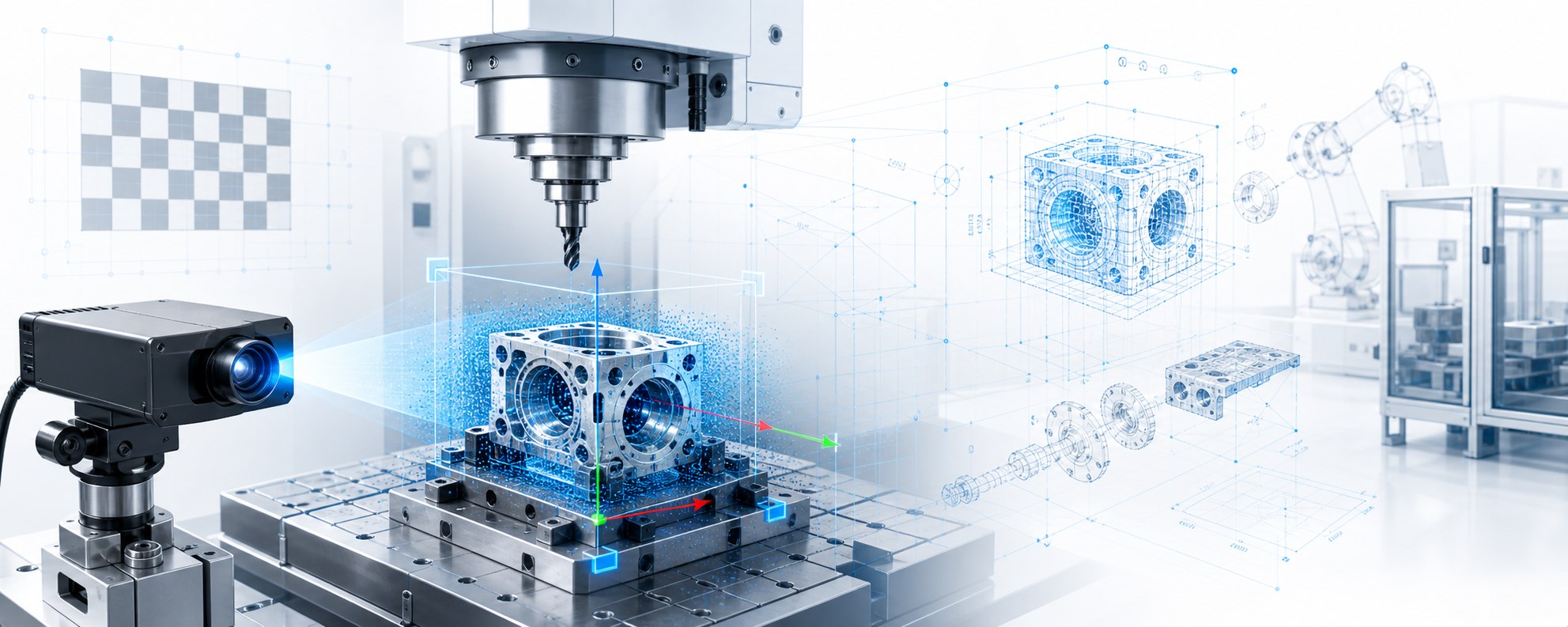
An industrial vision system for part recognition and 6D pose estimation, using RGB-D data, a corrected point cloud, YOLO detection and FoundationPose.
Project Overview
From camera image to a usable part pose
The project combines object detection, camera calibration, point cloud correction and CAD-based pose estimation into an engineering workflow for machining and automation processes.
An intensity image, depth image and camera parameters provide the geometric foundation.
Part localisation, class identification and a region of interest for pose estimation.
STL models are combined with the corrected RGB-D data to determine the 6D pose.
Multiple views can further refine the pose and reduce measurement deviations.
Pipeline
Geometry correction comes before FoundationPose
FoundationPose works with RGB-D and point cloud data. Camera and depth geometry are therefore prepared carefully before the pose is calculated.
-
01
Capture RGB-D Data
The camera supplies intensity, depth and intrinsic parameters.
-
02
Calibration
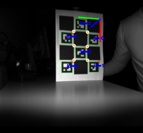
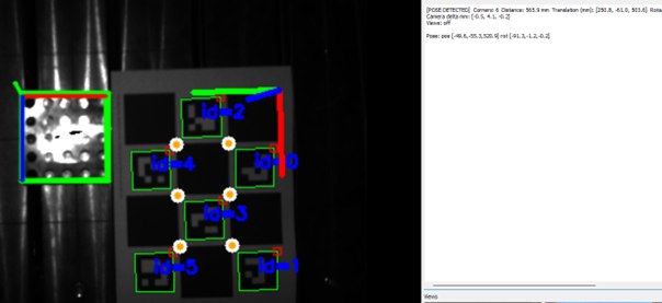
ChArUco and hand–eye data connect the camera, tool and coordinate systems.
-
03
Correct the Point Cloud
Fisheye and depth deviations are corrected before pose estimation.
-
04
YOLO Detection
The part is detected, classified and passed to the pose stage as a region of interest.
-
05
FoundationPose
The matching CAD model is aligned with the corrected RGB-D geometry.
-
06
Pose Output
The output is a 6D pose with translation, rotation and optional ICP refinement.
01 / Calibration
Preparing the camera, tool and coordinate systems
Calibration provides the foundation for evaluating image data, depth data, robot pose and part geometry in a common coordinate framework.

02 / Geometry
Point cloud correction before pose estimation
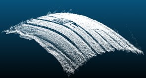
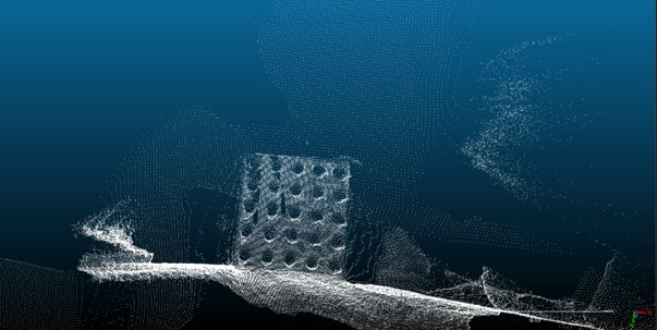
The depth image and point cloud are corrected before FoundationPose. This gives the algorithm a more consistent representation of the part geometry instead of distorted raw data.
Show image comparison
The gallery shows the difference between the distorted point cloud, the corrected point cloud and a scene view. This step was important because pose estimation depends directly on the quality of the depth geometry.
03 / Detection
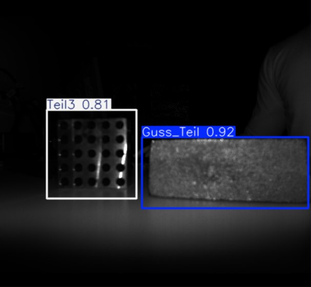
YOLO supplies the class and region of interest
YOLO performs rapid object detection. The detected class determines which CAD model to use, while the bounding box limits the area for subsequent pose estimation.
04 / Pose Estimation
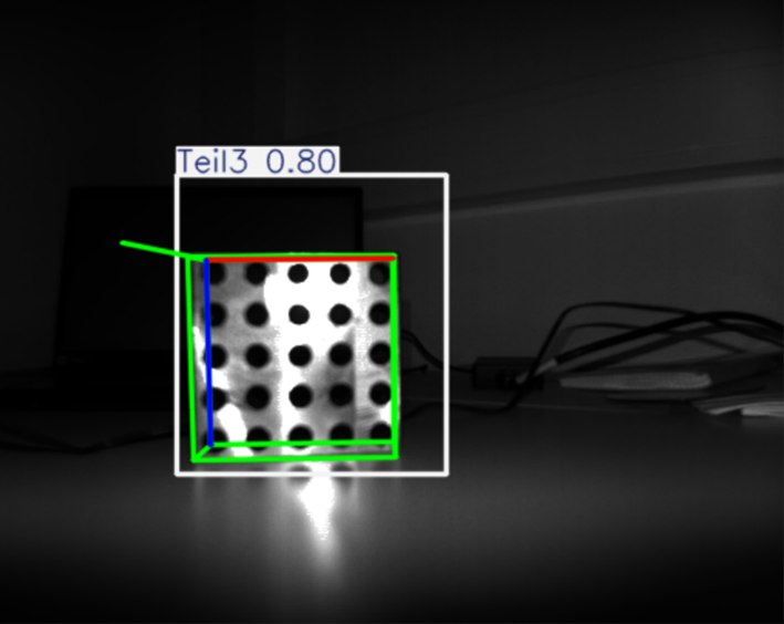
FoundationPose on corrected RGB-D geometry
FoundationPose uses the corrected geometry and matching CAD model to determine the part’s 6D pose. The output can then be used for machining, inspection or subsequent robotic operations.
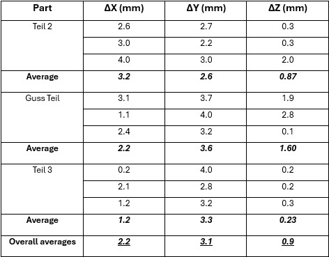
Show validation
The results were assessed against measurement and reference data. The accuracy table records positional deviations and shows where calibration, depth correction and pose estimation needed improvement.
05 / Integration
Software pipeline for testing and evaluation
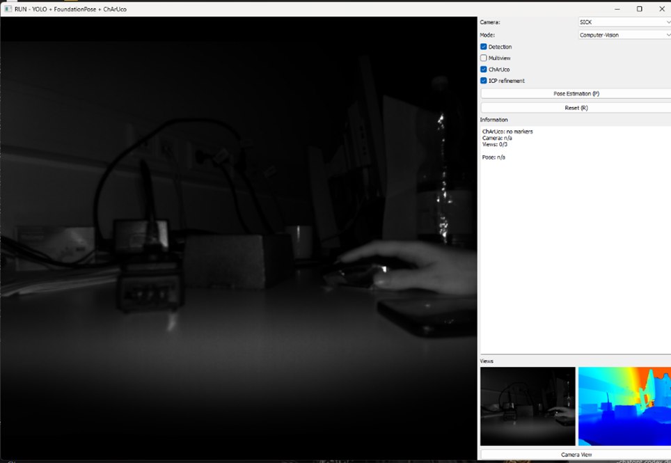
The software connects the camera input, YOLO model, CAD data, FoundationPose, point cloud view and result visualisation. This enabled iterative testing and improvement of the complete process.
06 / Practical Testing
Testing phase
This testing phase checks whether YOLO detects parts and opens the corresponding STEP file for each one.