Simulations, Finite Element Analysis and Validation
Structural simulation, load-case assessment and geometric validation of a welded spaceframe: from torsional stiffness and bracket stresses to CAD-to-scan deviation analysis.
Scope of Work
Using simulation results to inform engineering decisions
These analyses connect defined load cases, finite element results, physical measurement methods and design decisions. The focus is on stiffness, local stresses, manufacturing effects and traceable engineering assumptions.
Target torsional stiffness of the spaceframe.
Measured stiffness, approximately five per cent above the target.
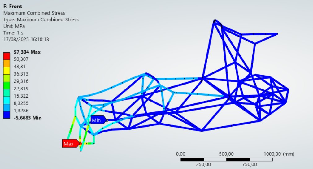
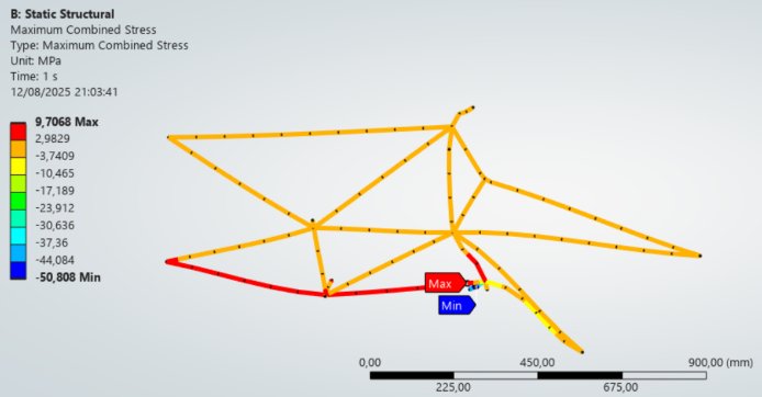
Maximum combined stress in the front load case considered.
Approximate maximum CAD-to-scan deviation at measurement points.
Structural Simulation
Spaceframe stiffness and mechanical load cases
The simulations assess whether the frame transfers loads between the front and rear axles in a controlled way and whether critical brackets are adequately sized.
01 / Torsional Stiffness
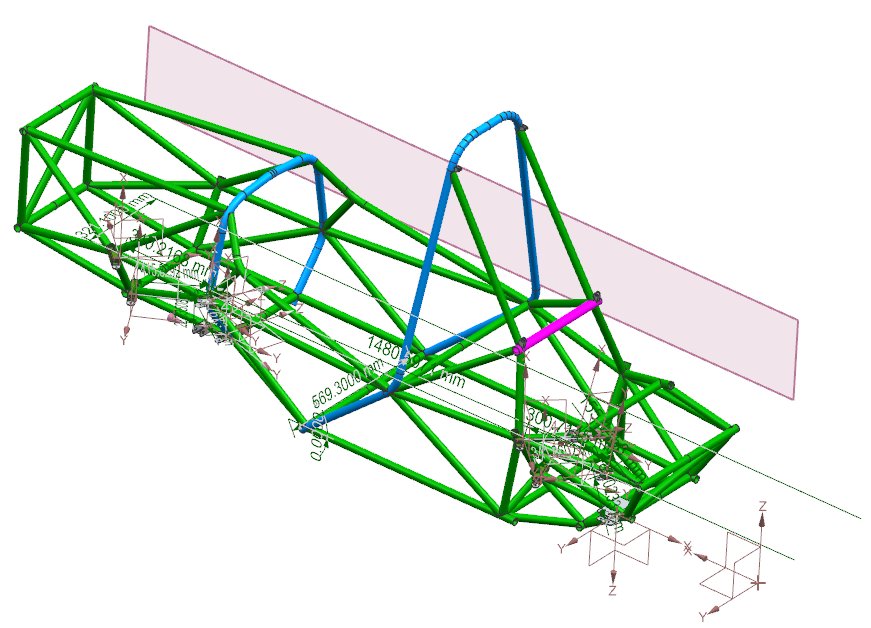
Torsional stiffness of the welded spaceframe
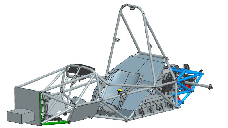
The spaceframe was designed to meet a defined stiffness target and assessed against it using finite element results and a measurement concept.
Show details
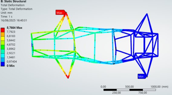
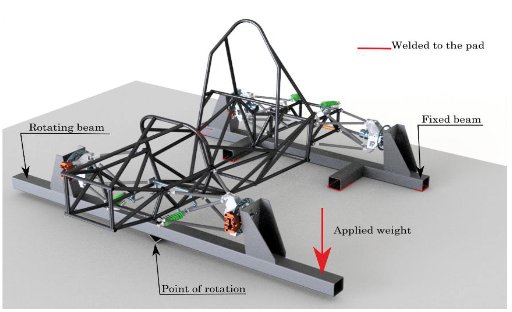
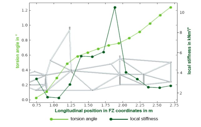
A torque was applied to the frame using defined forces and lever arms. The simulation shows the resulting deformation, while the test concept describes practical validation using a locked suspension, fixed supports, a rotating side, weights and displacement measurement. The achieved result exceeds the target and confirms that the structure can transfer torque between the front and rear axles with sufficient stiffness.
02 / Finite Element Stresses
Aerodynamic, bracket and mounting load cases
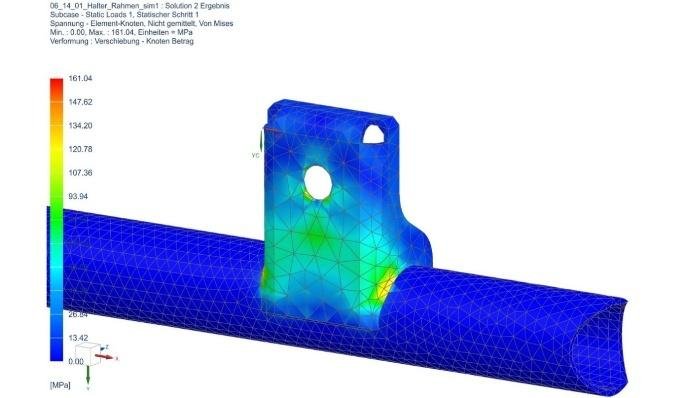
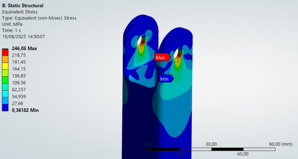
Critical connection points were studied using defined forces, support conditions and stress plots to reveal local stress concentrations and deformation.
Show details
The assessment covers global frame load cases and local bracket analyses. Boundary conditions, force vectors and mesh models were configured to reveal critical areas at mounting points and transitions. The results informed component geometry, wall thicknesses, bolted connection areas and design clearances.
03 / Suspension Loads
Load-case assessment for suspension and pushrod mounting points
Suspension areas were assessed using static load assumptions, friction coefficients and bump/cornering scenarios. The aim was to size the frame’s load introduction points robustly.
Show details
Force components were considered in tension and compression and translated into frame load cases. This revealed critical areas before the geometry was finalised. Differences between local joints, lugs and adjacent tube sections were particularly important.
Validation
Bringing simulation, measurement and geometry checks together
Alongside stress and deformation, the work examined actual manufacturing quality: the CAD model, 3D scan and measurement points were compared to interpret deviations in engineering terms.
02 / Finite Element Stresses
Aerodynamic, bracket and mounting load cases
Critical connection points were studied using defined forces, support conditions and stress plots to reveal local stress concentrations and deformation.
Show details
The assessment covers global frame load cases and local bracket analyses. Boundary conditions, force vectors and mesh models were configured to reveal critical areas at mounting points and transitions. The results informed component geometry, wall thicknesses, bolted connection areas and design clearances.
03 / Suspension Loads
Load-case assessment for suspension and pushrod mounting points
Suspension areas were assessed using static load assumptions, friction coefficients and bump/cornering scenarios. The aim was to size the frame’s load introduction points robustly.
Show details
Force components were considered in tension and compression and translated into frame load cases. This revealed critical areas before the geometry was finalised. Differences between local joints, lugs and adjacent tube sections were particularly important.
04 / 3D Scan Comparison
Geometric deviation analysis after manufacturing
The manufactured frame was checked against the CAD model. Suspension points, accumulator support tubes, parallelism and longitudinal deformation were particularly relevant.
Show details
The measured deviations fell within the functional adjustment and tolerance ranges. Smaller differences could therefore be compensated for using the adjustable suspension components. The analysis also documents how the fixtures and welding process affected the final geometry.
05 / Design Decision
Material and tube sizing informed by simulation and manufacturing
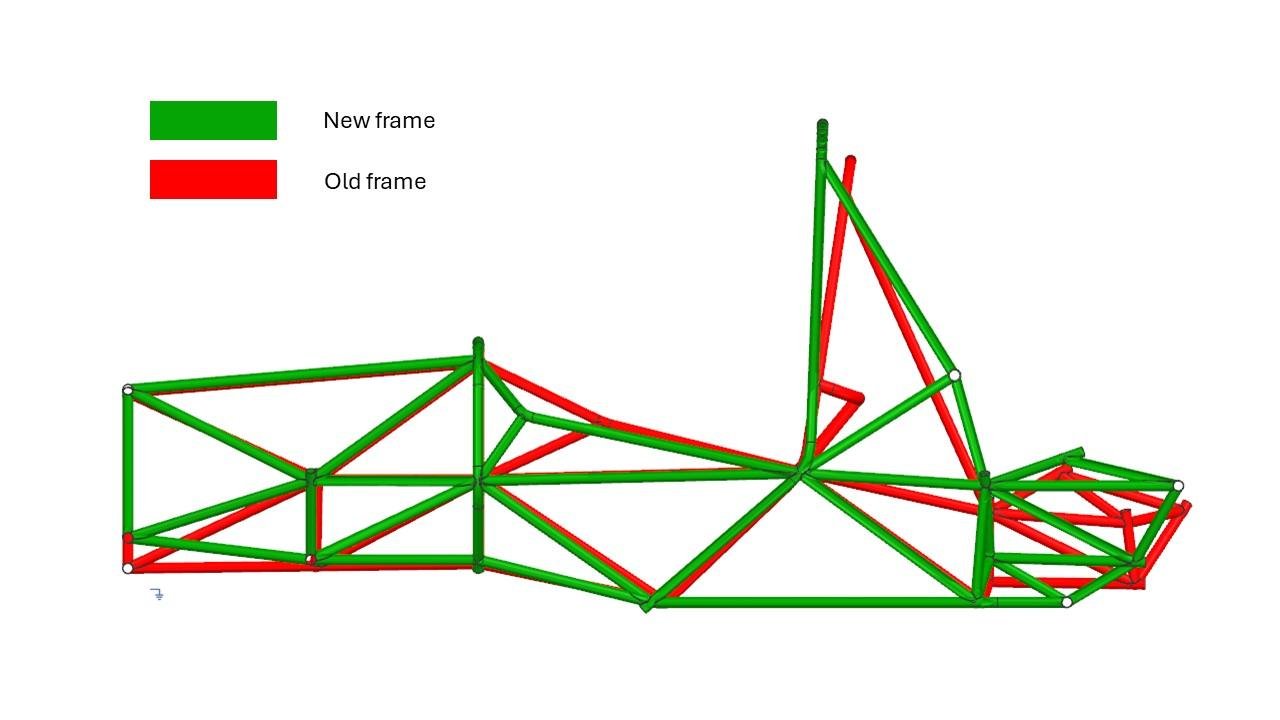
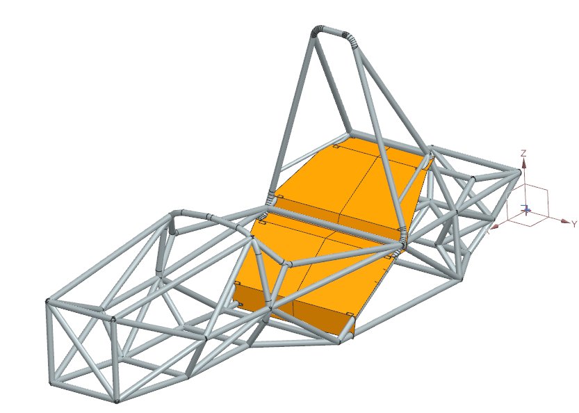
The frame design was assessed against more than weight alone. Availability, weldability, repairability, vehicle packaging and robust manufacturing within manageable tolerances were also decisive.
Show details
Several materials and tube dimensions were compared. E355 was preferred for its cost, availability, manufacturing risk and reliability. The final tube size of 25.4 × 1.6 mm offers a practical balance between weight, packaging, joint robustness, repairability and a lower risk of welding distortion or burn-through.