In Development
CAD automation with engineering context
From STEP model to a drawing ready for review.
I am developing DrawGen to reduce repetitive drawing work and make engineering decisions traceable. The prototype combines rule-based drawing generation with explicitly defined functional requirements and transparent calculation models.
Two documented examples
From a model to a traceable result.
The current workflow
Derive the geometry. Define the requirements. Review the result.
- Import the STEP model
Load a single part and set its orientation for the drawing views.
- Generate a drawing draft
Derive views, recognised features and proposed geometric dimensions.
- Define the function
Explicitly specify contact surfaces, mating dimensions and allowable size conditions.
- Calculate the limits
Check supported size comparisons and linear tolerance chains; apply the selected values.
- Define the manufacturing route
Document the material, operations, times and cost rates as a separate scenario.
- Refine and export
Review dimension placement and drawing notes, save changes and export SVG/PDF/HTML.
Technical decisions in the project
Three principles guide the implementation.
Separate geometry from function
A recognised hole initially describes a geometric shape. Additional information is needed to establish whether it provides guidance, fastening or simply clearance. Drawing datum symbols and functional contact definitions are also recorded separately.
Calculate from explicit inputs
Size checks use specified limits and mating dimensions. Costs are calculated from a documented manufacturing route. This makes it clear which results are calculated and which assumptions the user provides.
Keep results with the project
Native project storage brings together the model reference, requirements, calculation scenarios and drawing adjustments. The presentation corrections shown here are saved in the DrawGen project and exported through its drawing canvas.
Case study 01
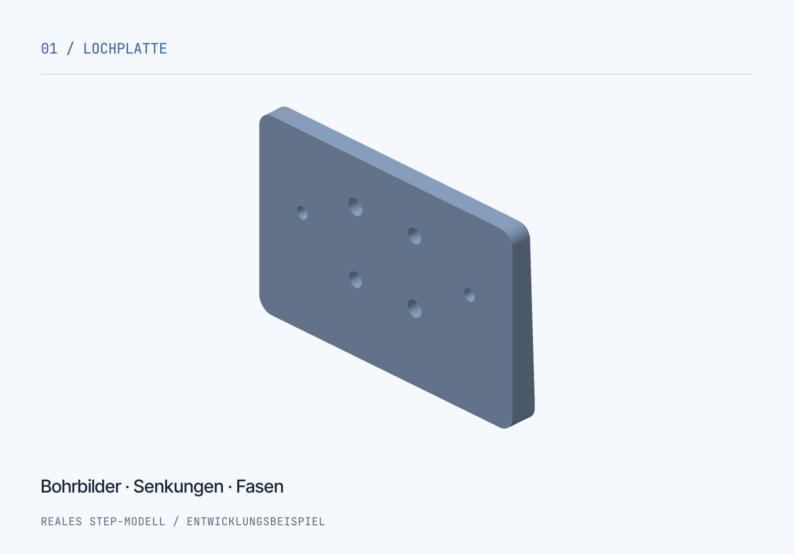
Drilled plate
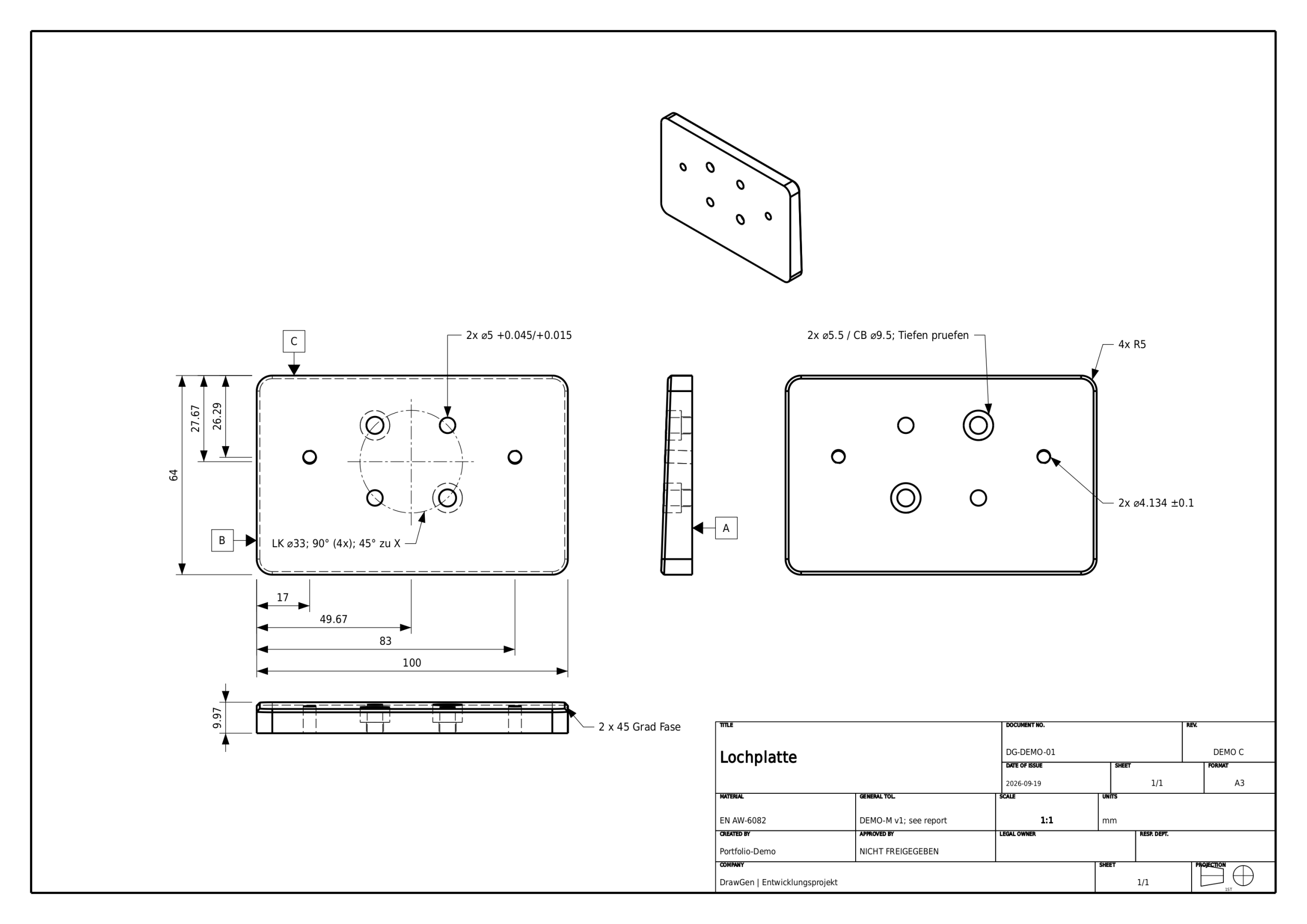
Five views show the component derived from the STEP model. The calculation checks whether specified hole limits meet the assumed diametral clearance requirement for a mating pin.
100 × 64 × approx. 9.97 mmEN AW-6082 / T651 · Example batch: 10 parts
Baseline dimensioning · Drawing revision C
Size check: hole and pin
- Allowable clearance · Demo requirement
- 0.020–0.100 mm
- Assumed pin diameter
- 4.960–4.980 mm
- Specified hole limits
- 5.015–5.045 mm
- Minimum diametral clearance
- 5.015 − 4.980 = 0.035 mm
- Maximum diametral clearance
- 5.045 − 4.960 = 0.085 mm
Result: The calculated interval lies entirely within the assumed clearance requirement. This conclusion applies to the size comparison under the stated assumptions.
Datums and interpretation
A: flat rear face · B: left side face · C: upper end face. These contacts illustrate an ideal 3-2-1 locating arrangement. They do not establish compliance with geometric tolerance zones.
Open items in this example
The M5 suggestions have not been confirmed as threads. Counterbore depths still require review. Identical diameter limits are grouped without implying a shared hole depth. The drawing is labelled as a demonstration and is not released for manufacture.
Case study 02
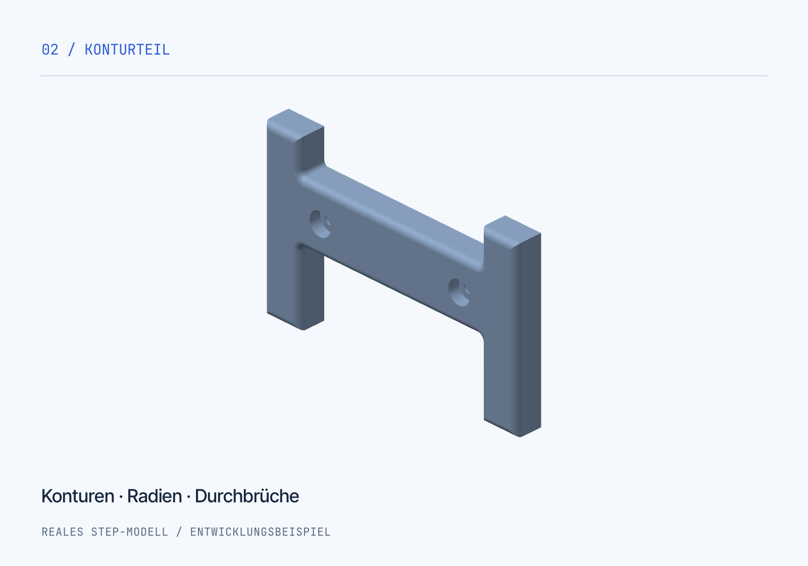
Contoured part
This example combines baseline dimensioning with a revised dimension layout. Both holes are assessed against an explicitly specified diametral clearance requirement for an assumed mating component.
120 × 75 × 12 mmEN AW-6082 / T651 · Example batch: 10 parts
Baseline dimensioning · Drawing revision C
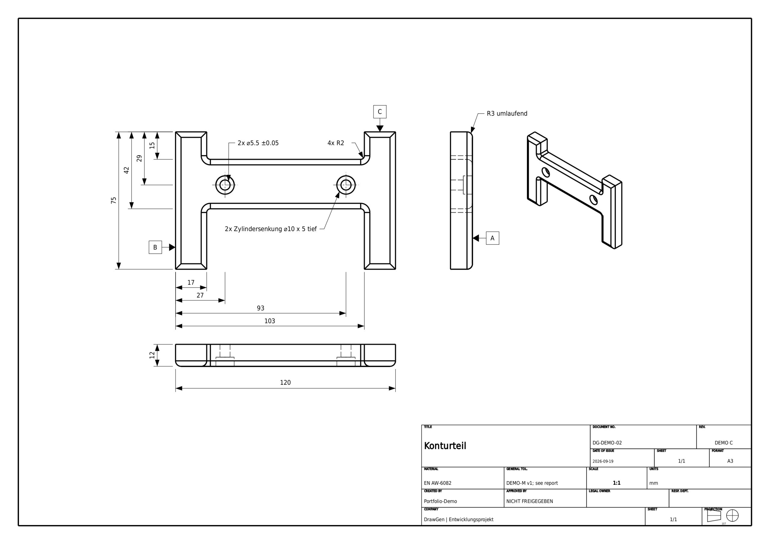
Size check: hole and mating component
- Allowable clearance · Demo requirement
- 0.400–0.700 mm
- Assumed mating diameter
- 4.980–5.000 mm
- Hole Ø5.5 ±0.05 mm
- 5.450–5.550 mm
- Minimum diametral clearance
- 5.450 − 5.000 = 0.450 mm
- Maximum diametral clearance
- 5.550 − 4.980 = 0.570 mm
Result: The calculated interval lies entirely within the assumed clearance requirement. Actual assembly function requires additional requirements and checks.
Datums and interpretation
A: rear supporting face · B: left outer face · C: upper-right end face. Drawing symbols A/B/C and confirmed functional contact surfaces are separate inputs.
Scope of the conclusion
The clearance calculation evaluates diameter limits. It does not cover hole positions, form, orientation or loads. No approved mating component is available; the values describe a deliberately defined demonstration scenario.
Development status and next steps
What works today. What comes next.
Available in the prototype
- STEP import for single parts, orientation, and orthographic and isometric views.
- Feature-based dimension proposals, baseline, chain and coordinate dimensioning, and manual additions.
- Drawing datum symbols, separate functional contact definitions and title-block information.
- Explicit size limits, fixed mating dimensions, worst-case clearance and supported linear tolerance chains.
- Local material, process and cost profiles with documented operations and calculation assumptions.
- Applying results to the drawing, undo/redo, native project saving and SVG/PDF/HTML export.
Not yet fully implemented or validated
- Drawing quality: broader geometry coverage, unambiguous grouping of different hole depths, robust annotation placement, and extended section and detail views.
- Numerical robustness: consistent tolerance-range assignment at boundary values. Numerical residue can currently affect classification; robust handling remains under development.
- Functional verification: comprehensive GPS/GD&T checks, geometric tolerance zones and physical datum simulation.
- Assembly context: assistance in identifying relevant component relationships, with proposals for user confirmation.
- Manufacturing assessment: automatically derived machining times, cost estimates calibrated against reference data, and a qualified product-release process.
- Integrated PLM module (planned): structured part and document management, revision control, traceable changes, and role-based review and release workflows. Interfaces to existing PDM/PLM systems are a longer-term objective.
An additional calculation example
Costs built from documented assumptions.
The cost model calculates scenarios from material, batch size and a defined manufacturing route. The values below use assumed times and rates for CNC manufacturing in Germany. Comparable supplier quotations or measured CAM times are not yet available for these examples.
Tolerance checks and cost calculations each have their own inputs. To make a reliable claim about the cost of a tighter tolerance, the manufacturing route must be adjusted and supported by evidence. This demonstration does not yet establish such an automatic connection.
Explore material and batch-size scenarios
Manufacturing cost per part, excluding VAT · Batch size 10 · Rounded model value; assumed scenario range below.
| Part | Aluminium EN AW-6082 / T651 |
Steel S235JR / hot-rolled |
Stainless steel 1.4301 / solution-annealed |
|---|---|---|---|
| Drilled plate |
approx. €64 approx. €37–€114 |
approx. €74 approx. €42–€132 |
approx. €90 approx. €52–€161 |
| Contoured part |
approx. €72 approx. €42–€129 |
approx. €84 approx. €48–€151 |
approx. €106 approx. €61–€188 |
The ranges represent assumed low and high scenarios, not statistical confidence intervals. Geometry remains unchanged in the material comparison. Material suitability for a specific application requires separate assessment.
View the main cost assumptions
Assumed hourly rates: €65 / €85 / €110 per hour. Time allowances: 75 / 100 / 140% of the base time. Material assumptions: aluminium €7 / €10 / €15 per kg; S235JR €1.50 / €2.50 / €4 per kg; 1.4301 €5 / €7 / €11 per kg. Sawing: €3 / €5 / €8 per blank. These prices and time factors are explicitly assumed scenario inputs.
Blanks: drilled plate 105 × 70 × 12 mm; contoured part 125 × 80 × 15 mm. Material cost uses the entire blank, including material removed during machining. Assumed densities: approximately 2.71 / 7.85 / 7.90 g/cm³.
Aluminium base times (drilled plate / contoured part): programming 45 / 50 minutes per batch; setup 40 / 35 minutes per batch; machining 18 / 22 minutes per part; deburring 4 / 5 minutes per part; inspection 6 / 6 minutes per part. Machining-time factors: steel 1.35, stainless steel 1.80. These are planning assumptions, not automatically derived CAM times.
Also included: fixture allocation, tool wear and packaging. No external surface treatment or additional scrap quantity is assumed. The optional price assumption adds 15% to manufacturing cost. VAT, shipping, certificates, rush charges and supplier-specific minimum-order requirements are excluded. The scenario range is not a statistical confidence interval.
Testing and interpretation
Test geometries with varying coverage.
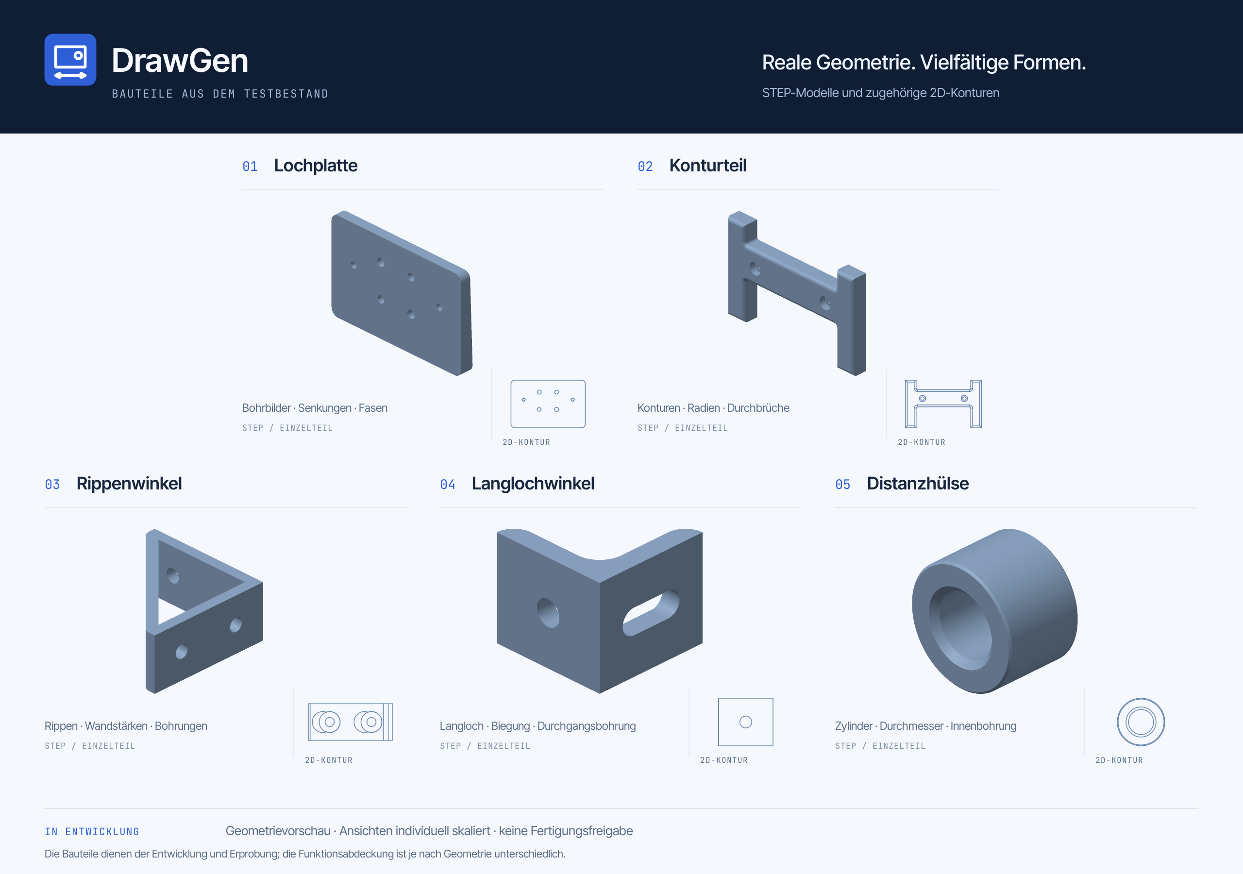
The two case studies show the developed demonstration examples. Additional models extend geometry testing. Feature coverage and drawing requirements are assessed separately for each part.
View additional test geometries
Tolerance basis and technical limitations
The local “DEMO-M v1” policy uses the publicly listed medium linear tolerance ranges in the linked Protolabs overview: 0.5–3 mm ±0.1; over 3–6 mm ±0.1; over 6–30 mm ±0.2; over 30–120 mm ±0.3; over 120–400 mm ±0.5. Individually specified size limits take precedence. This versioned example profile does not establish full DIN/ISO conformity.
Mating dimensions, clearance requirements, contact functions, Ra 3.2 µm, tool accessibility and workholding are assumptions for this demonstration. No approved mating components or process-capability evidence are available. Geometric tolerances, loads and assembly function require their own checks. The unresolved handling of numerical residue at tolerance boundaries is listed in the development status.