Major Engineering Projects
From 120 kg handling systems to high-speed can rotation: five projects in mechanical design, handling systems, automation and technical documentation.
01
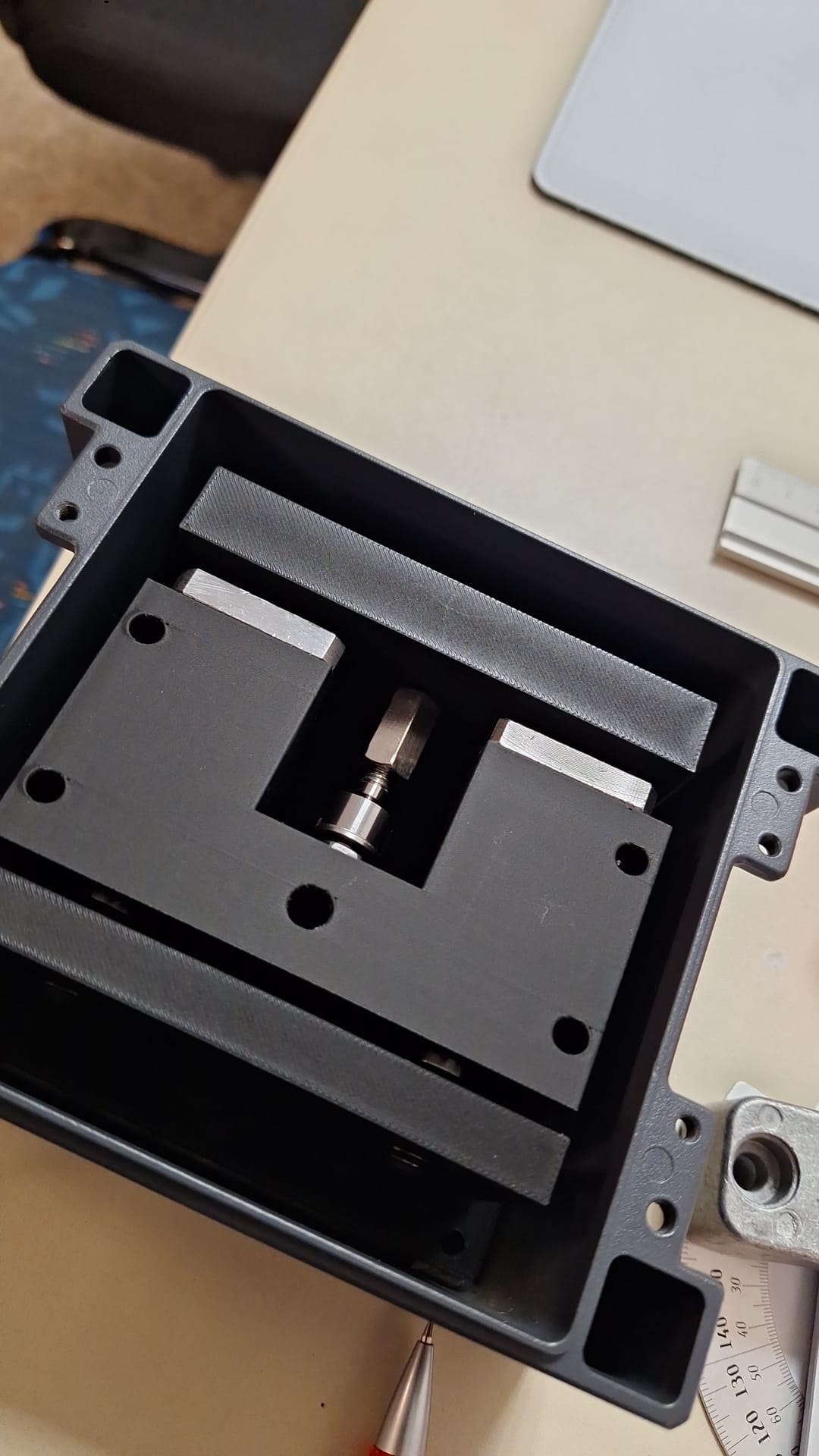
120 kg Handling System for Meat Cages
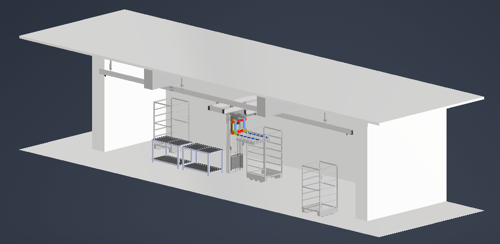
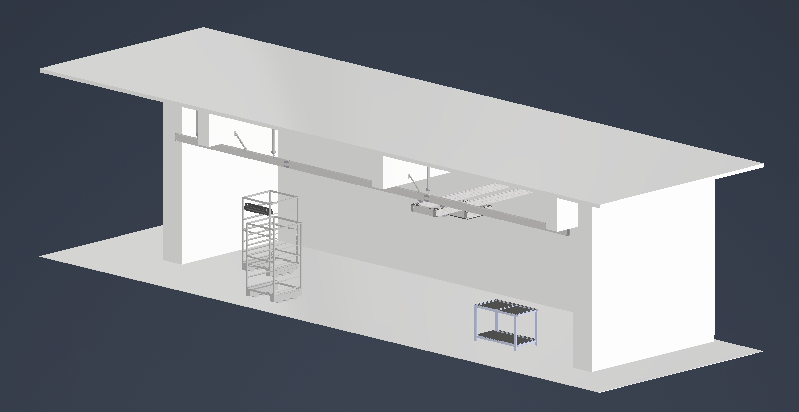
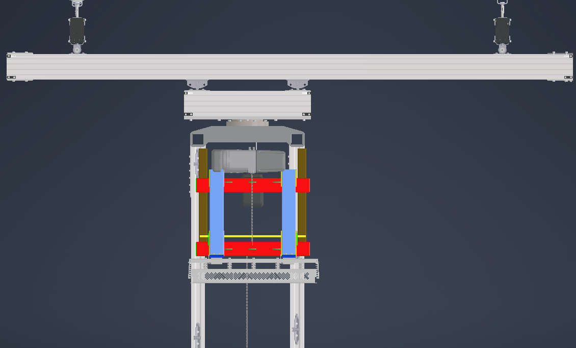
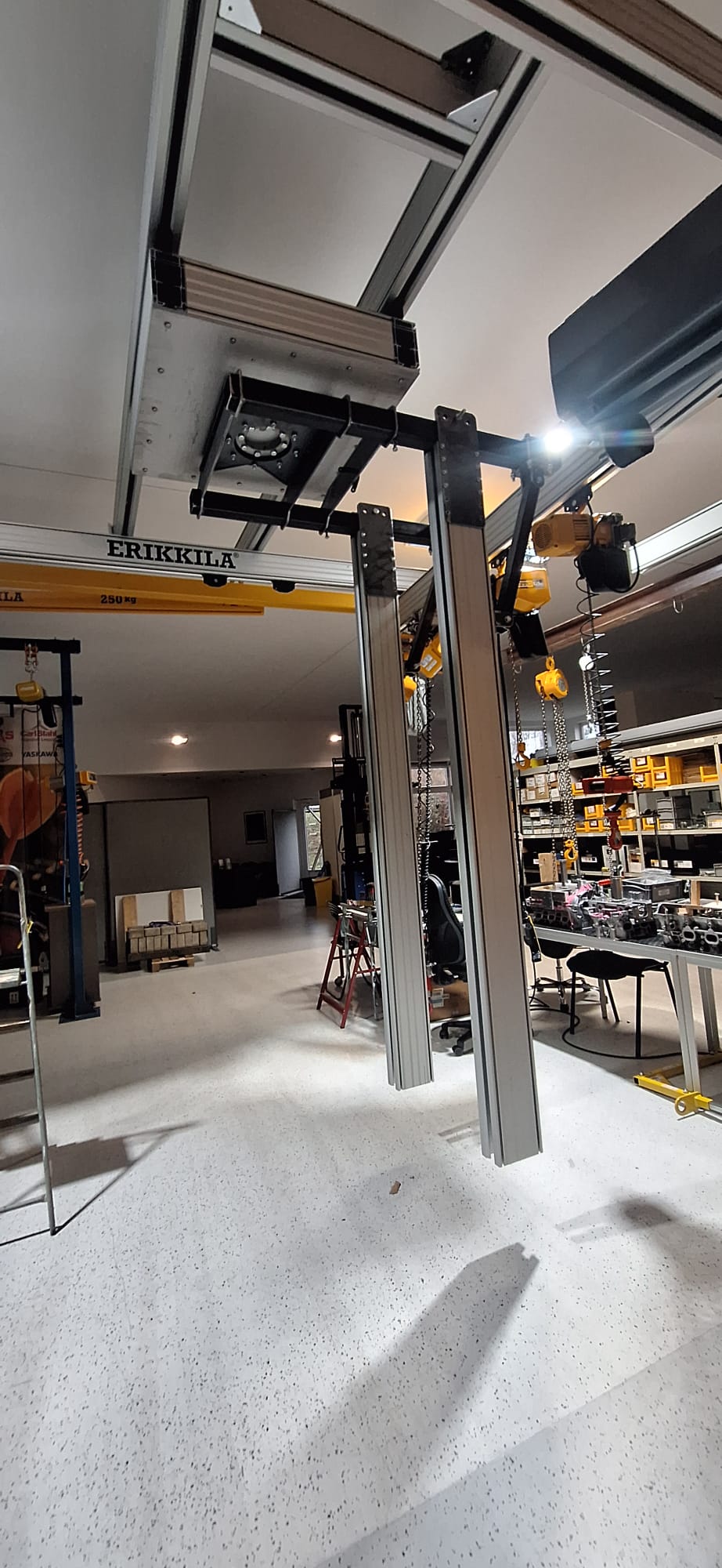
Design of a large handling system for an industrial hall measuring approximately 16,000 × 5,000 mm. The system moves along the X, Y and Z axes and allows 360° rotation around the Z axis.
Show more
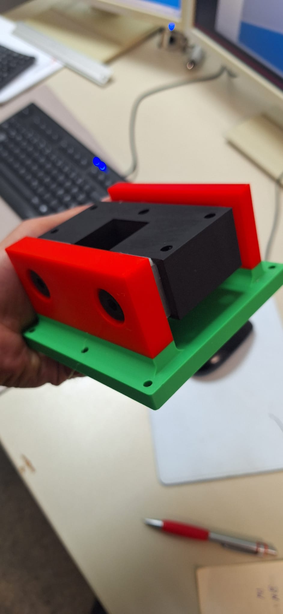
This project required simultaneous consideration of available space, the food-processing environment, material selection, weight, load handling and stress analysis. Numerous individual parts were also designed to position, move and control the lifting attachment safely. One important detail was the sensor housing: its dimensions had to allow tilt movement to be detected accurately and the system’s Z movement to be controlled reliably.
02
Robot Gripper with 180° Box Rotation
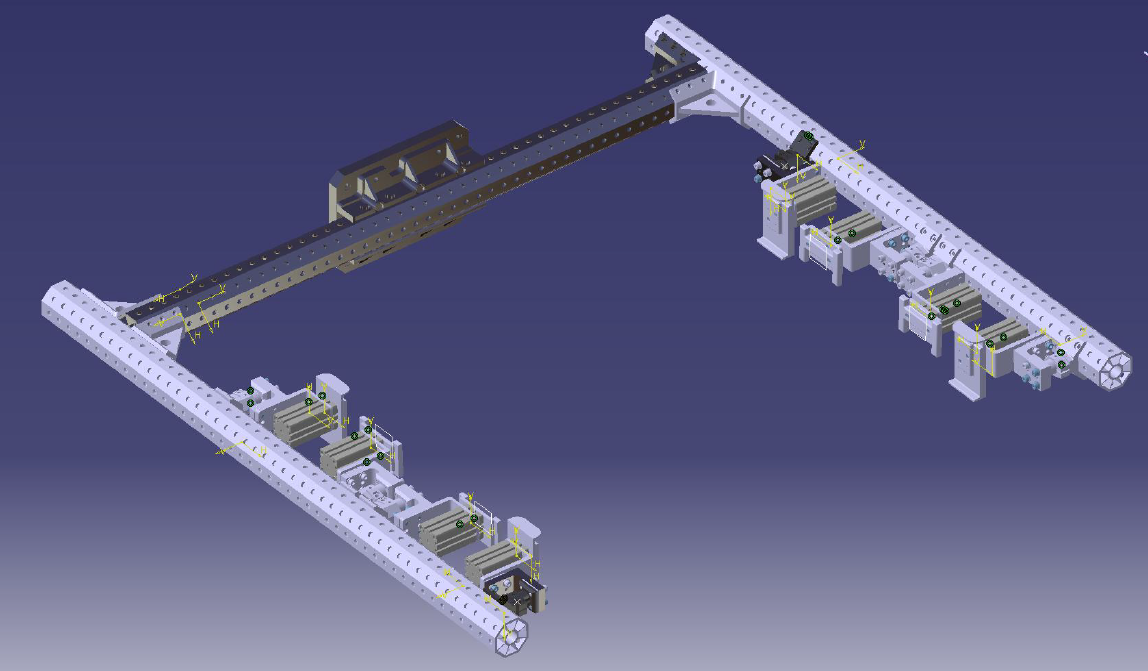
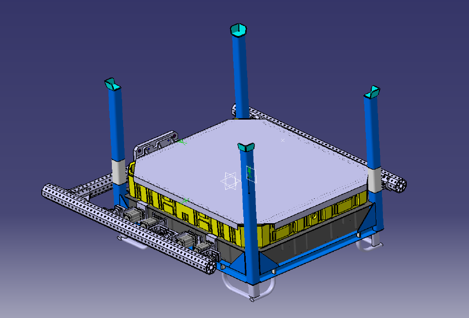
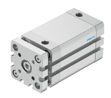
Development of a gripper for boxes weighing up to approximately 15 kg, using pneumatic actuators, EGT aluminium profiles and custom-designed end effectors.
Show more
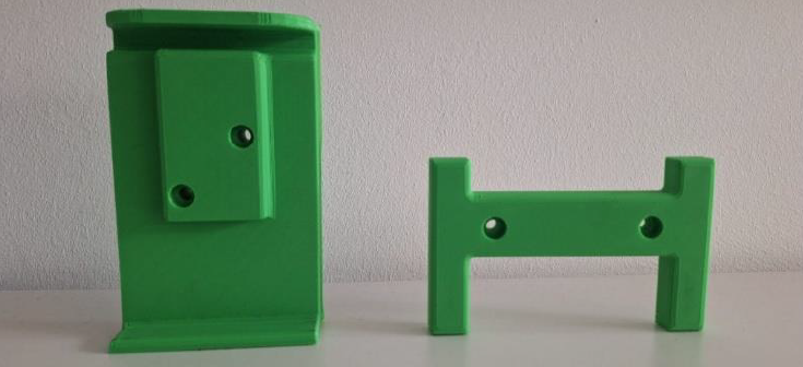
The internship report specifies that the gripper should secure the box along the X, Y and Z axes to enable stable 180° rotation. The design was developed in CATIA V5, including the frame, actuator selection, positioning, installation clearances, end effectors, 3D-printed prototypes, 2D drawings and bill of materials. Tolerances, contact surfaces, safety clearances and mechanical integration with the robot arm were particularly important.
03
180° Can Rotation on a Production Line
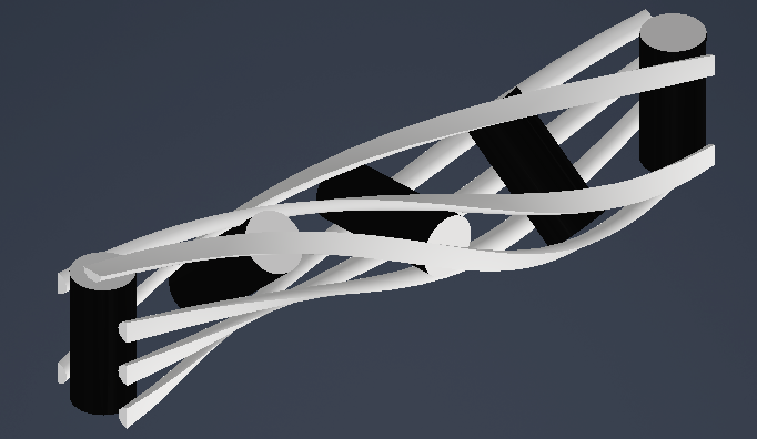
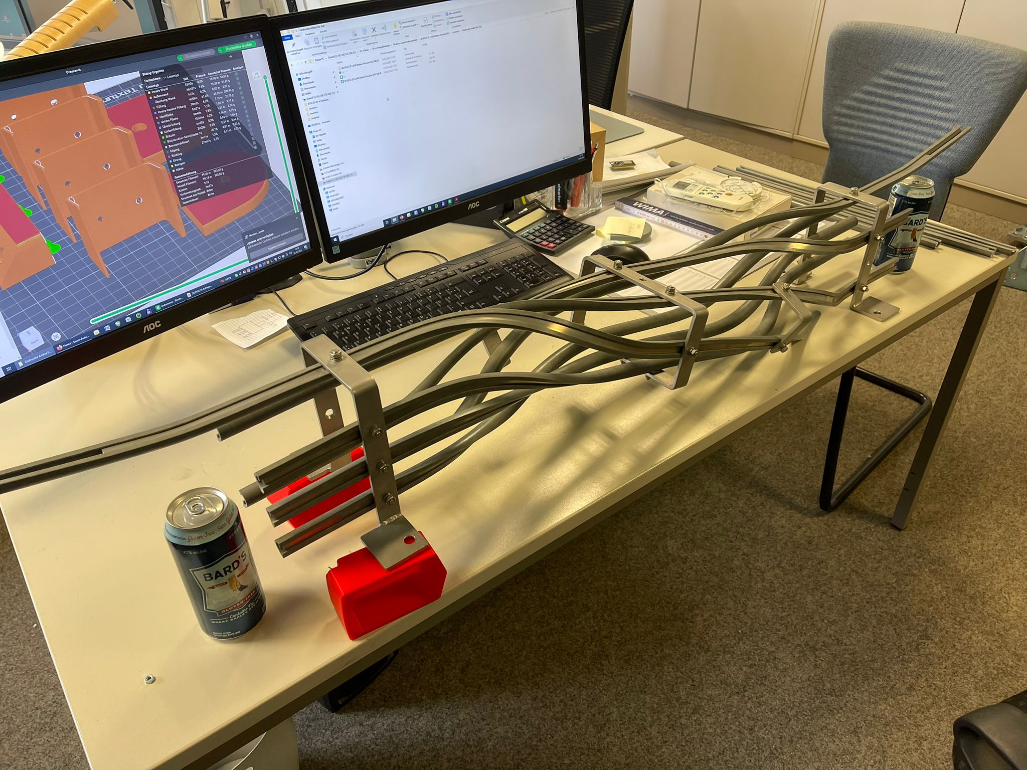
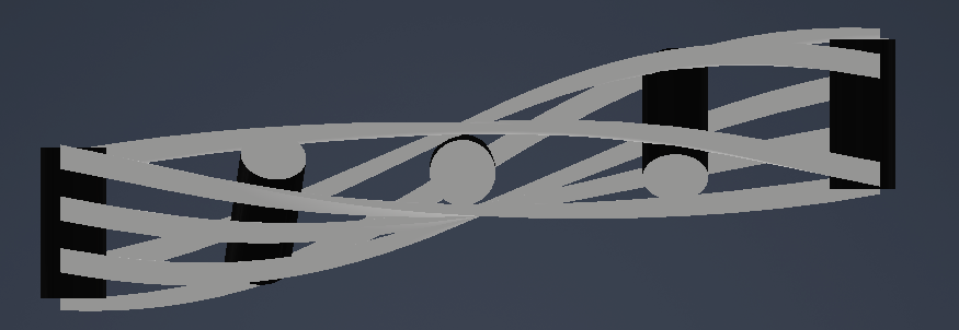
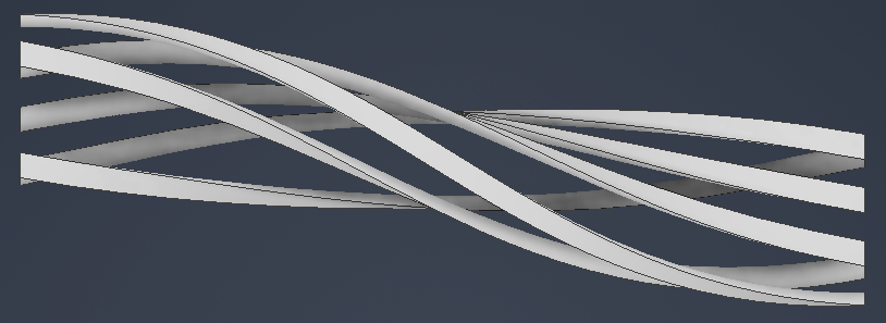
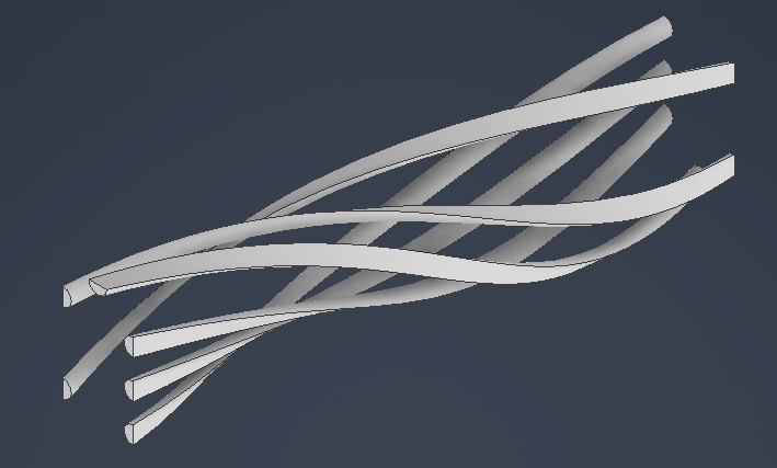
Development of a mechanism to rotate a can through a controlled 180° movement within a confined space during high-speed mass production.
Show more
The aim was a smooth, gentle rotation with as little friction as possible against the can surface. The challenge was the limited travel distance, high throughput and need for repeatable rotation without disrupting the existing production flow.
04
Twin-Turbo V6 Engine — Independent CAD Project
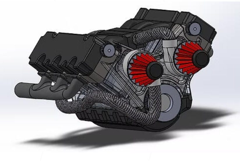
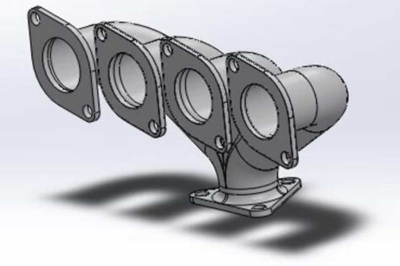
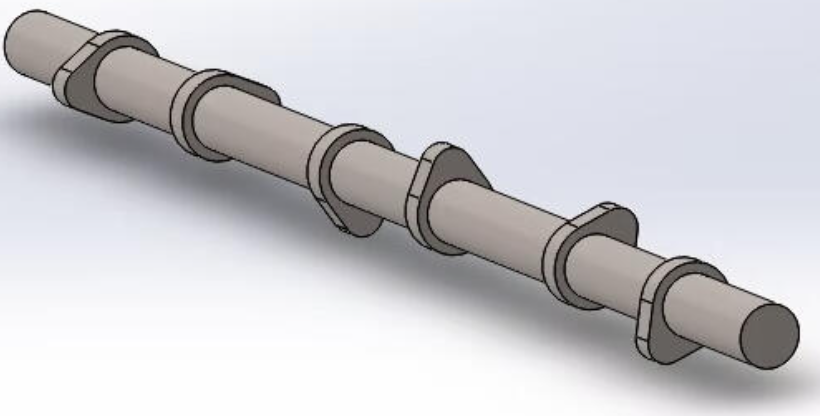
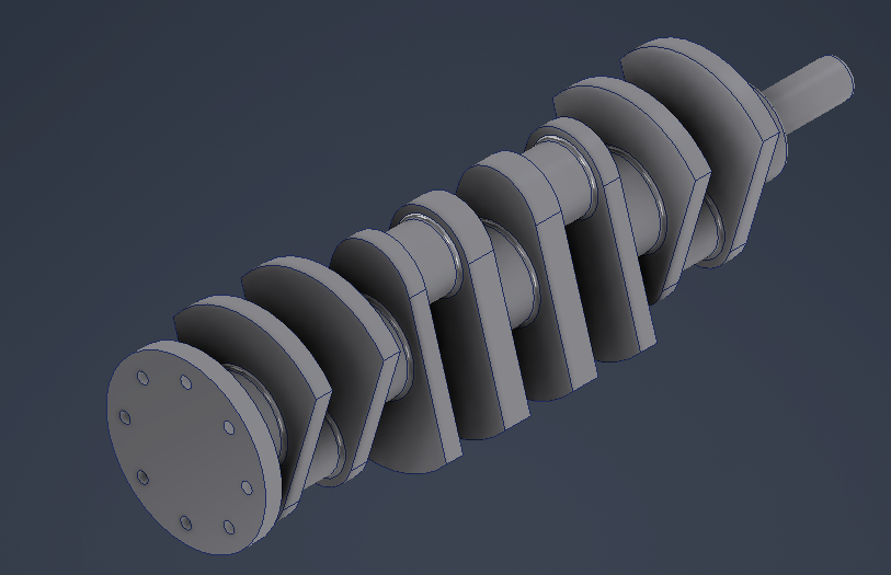
An independently completed CAD project involving detailed 3D modelling of a complex engine with many individual components.
Show more
The individual part drawings provided the basis, and I completed the 3D modelling independently. The complexity comes from the number of parts, turbochargers, pipe routes, manifold geometries, shafts and housings. Accurate proportions, clean geometry and a clearly structured overall assembly were essential.
05
Pneumatic Assembly for Demonstration
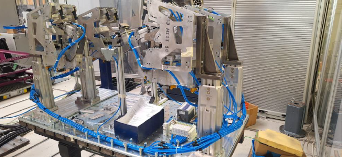
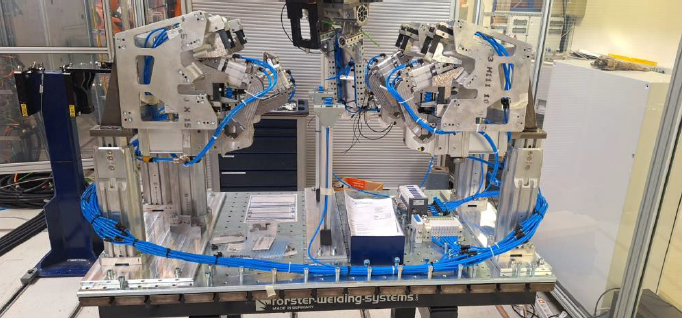
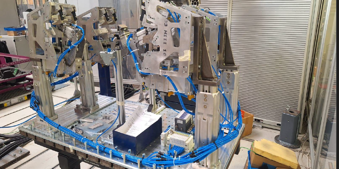
Development of symmetrical pneumatic hose routing for multiple actuators, including control positions and a connection layout.
Show more
This project required numerous hoses to be connected to pneumatic actuators in an orderly, functional and visually clear arrangement. Because the assembly was used for demonstrations, symmetry, accessibility, understandable connections and clear positioning of the controls were particularly important.